|
MODEL 5A Microelectrode
Amplifier 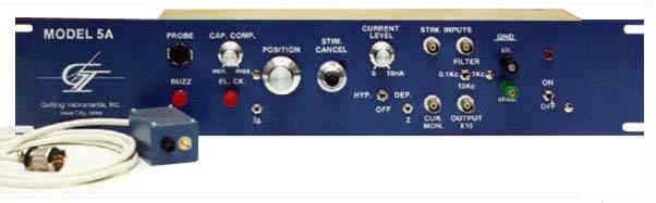
Description:
The Getting MODEL 5A
MICROELECTRODE AMPLIFIER is a low-noise amplifier
designed for intracellular recording and stimulation. It
consists of a main rack-mountable chassis (blue with
white letters) containing all the controls and a small
remote probe housing the input head-stage. This amplifier
has a number of controls that are useful for
intracellular recordings, such as Capacitance
Compensation, "Buzz", Electrode Impedance
Check, Bridge Balance (Stimulus Cancel) , and Position.
Current can be injected either by an internal DC Current
Level control or by two external Stimulation Inputs, and
the total injected current is available at the Current
Monitor output. The Output can be filtered at 0.1, 1.0,
or 10.0 kHz and has a gain of x10.
Theory of
Operation:
Input Probe: The
input probe consists of a small box (1.25" x
1.25" x 2") connected to the main chassis by a
five-foot flexible cable. Microelectrodes are connected
to the probe via a flexible shielded cable up to 14"
in length. The shield of the cable is driven to reduce
capacitance and increase rise- time. Since the electrode
is not connected directly to the probe housing, a variety
of electrode holders can be used to suit your particular
requirements. The unit is provided with two (2) input
cables.
Amplification: A
single x10 output is provided (BNC connector). A
selectable high frequency output filter (Low Pass Filter)
is built in with cutoff frequencies of 100 Hz, 1 kHz, and
10 kHz.
Capacitance Compensation:
Stray capacitance can be compensated by adjusting a
10-turn potentiometer on the main chassis. In addition,
the MODEL 5A is equipped with a "BUZZ" button
which causes the amplifier to oscillate. This feature is
useful for penetrating cells without having to change the
capacitance compensation setting.
Current Injection:
Current can be injected through the microelectrode while
simultaneously recording membrane potential. The MODEL 5A
provides both a built-in current source and two external
inputs. The built-in source is controlled by a switch for
current polarity (hyperpolarizing, off, depolarizing) and
a potentiometer for current magnitude (range 0-10 nA).
Externally applied voltage waveforms can be converted
into current stimuli of the same waveform. Two external
stimulus inputs (BNC connectors) are provided. Signals
applied to these inputs sum internally so that complex
current waveforms can be achieved easily.
Voltage-to-current conversion is 1 nA per 100 mV. A
current monitor output (BNC connector) is provided which
measures the total current injected through the
electrode. Calibration: 1 nA/l00 mV.
Bridge Circuit: The
bridge circuit cancels the voltage generated by the
electrode during current injection. The standard bridge
is equipped with a 10-turn potentiometer and is for use
with electrodes up to 200 megohms; however, the bridge
can be modified for use with higher resistance
electrodes.
Position Control:
Adjusts the DC output level with a 10-turn potentiometer
on the main chassis.
Electrode Test: The
resistance of the electrode is measured by depressing an
electrode test button. Calibration: 1 megohm per l0 mV at
the output.
Power: Each main
chassis contains a regulated + 15 VDC power supply. The
AC power requirements are either 110 VAC (60 cycles) or
220 VAC (50-60 cycles).
| Microelectrode Amplifier
Specifications |
| Input impedance |
1011 // 2 pF
min. (typically > 1011 ohms) |
| Input voltage range |
+/- 1 Volt |
| Output |
Single-ended, gain xl0
(fixed) |
| Output impedance |
Less than 100 ohms |
| Output filters |
Three selectable ranges;
DC to 100 Hz, DC to l kHz, DC to 10 kHz |
| Rise-time |
40-50 microseconds (with
10 megohm source resistance and capacitance
compensation adjusted for no overshoot) |
| Noise |
40 microvolts RMS (200
microvolts peak-to-peak), DC-b Kc with 10 megohm
source resistance |
| Leakage current |
Adjustable to zero |
| Current injection |
Mode A: Built-in DC source
with adjustable magnitude (0-10 nA standard) and
switchable polarity Mode B: Two external inputs convert
voltage to current (1 nA per 100 mV).
|
| Maximum current: |
5 volts or 10 amps /
elect. resist. |
| Current monitor |
Built-in current monitor
measures total current injected through the
electrode Calibration: 100 mV per nA |
| Electrode test |
Electrode resistance test
button built-in |
| Capacitance
compensation |
Capacitance
compensation |
| Ground |
Chassis and circuit
grounds are isolated |
|